 |
The rehabilitation |
|
|
The rehabilitation |
|
As vast and ubiquitous as the internet seems to be, one can still occasionally come upon a subject that seems to be nearly nonexistent in cyber space. Such has seemed to be the case with my recently (Jan. 2005) acquired milling machine. Therefore this page shall be my attempt to remedy this situation. Perhaps someone else might benefit from or be able to contribute to its content someday. You may note that I use the word rehabilitate rather than restore. This is because I have little intention of cosmetic restorations, preferring rather to bring this unit up to sound mechanical condition as a working member of our farm shop. I set no deadlines or goals, I will not clean or paint anything that does not require it for proper operation. I have no experience in, or resources for, hand scraping so the ways will have to serve in their present condition. There is, however, still evidence of what I assume to be the factory scrape marks.
First for a little history...
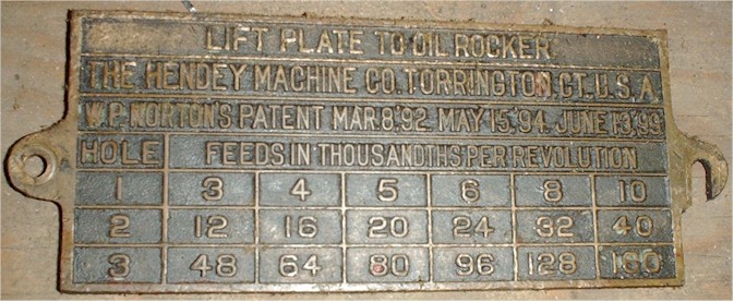
The Hendey Machine Tool Co. was officially begun around 1873 by Henry and Arthur Hendey in Torrington, CT. The company produced a variety of machine tools and quickly acquired a reputation for quality materials and workmanship. A more in depth history can be found here. The company began producing mills in the early 1890's and incorporated Wendell Norton's patented QC gear box into the design. The index plate indicates the latest patent date to be June 13, '99 and since I know they don't mean 1999 this mill could possibly pre-date World War I. Exact dating appears impossible as there are no known records of Hendey Milling machine manufacture surviving from this era.
Now to the nitty gritty...
Specifications ( at least those I can determine through measurement or theory. Recently amended. Thanks for the info, Hendeyman )
Model: 2B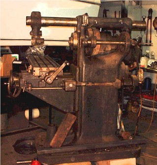
Serial #: 2686
Table Size: 10"x 45"
Longitudinal Travel: 25" w/ power feed
Cross Travel: 8" w/ power feed
Vertical Travel: 18" w/ power feed
Spindle Speeds: 8 bi-directional
(4 speed gear box w/ back gear and barrel switch)
Originally sold as sixteen speed with the use of a two
speed countershaft. Not used on this unit.
Feeds: 18 (.003 through .160)
Spindle Taper: B & S #10 (vertical attachment w/ B& S #9)
Spindle Bore: 1-1/16"
Weight: approximately 2600 lbs. ( a universal mill being 2675 lbs. )
Drive Motor: ( not original )
Voltage: 220
Phase: 3
The Good News...
The spindle runs smoothly in both directions. The electric motor is somewhat sluggish in high gear which does not concern me as I don't generally run high speeds. Also, the mill was originally designed to be run from a line shaft so I'm not going to lose sleep over the jury rigged power source that it uses now, as quaint as it is. I will continue to run it as long as it's serviceable.
The Bad News...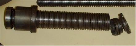
The second stage of the "Z" screw is broken! In three pieces no less! This is proving to be my greatest technical challenge. I think that this is most likely the result of moving the mill by sliding along the floor while the screw was contacting the floor. It is an object lesson to me that, should I ever need to move a similar mill in the future, the knee should be sufficiently elevated as to engage the second stage screw and get it off the floor. The evidence is in the base ring which is ground in a tapered fashion.
The Plan of Attack...
The piece in question consists of a cored gray cast iron round. It incorporates a full length external Acme thread of 2" x 4 tpi and an internal Acme thread of 1 1/4" x 4 tpi about 2 1/4" in length at the top flange end. The remainder of the internal bore is smooth and bored to 1.270 to provide thread clearance for the inner lead screw. I have decided to use the following machining progression. Recently revised.
First: Center drill both ends and true the exterior for steady rest work.
Second: The fun starts with deep hole drilling if I cannot find cored rod stock. I couldn't.
Third: Assuming I can bore a straight hole through the entire 12.25" length, I have to cut an internal Acme thread for the first 2.25" and then relief bore the rest to 1.270" for the inner lead screw clearance.
Fourth: Cut the lead in ramp for the engaging dog of the inner Z screw. You'll see...
Fifth: Mount the resulting piece on a precision mandrel (I don't trust my chucks to be precise enough) and turn outside diameters and shoulders to finished size.
Fifth: Cut the outer Acme thread.
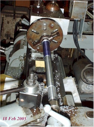
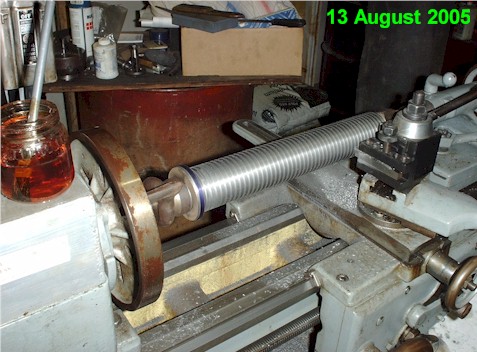
In order to hold the cored and internally threaded part for the outside threading I decided to create a centering mandrel which when finished will allow me to precisely hold and drive the part for the external threading. In creating the centering mandrel I have finally conquered a persistant problem that I had with my tailstock alignment. I now can hold +-.0005 tolerance or better over the entire 14" length! Not bad for a 1947 lathe and necessary to produce a proper mandrel. Note the blued area near the lathe dog indicates where the finished major diameter for the 1.250" Acme thread is. The rest of the shaft will be relief cut to provide clearance for the internal threads of the finished part.
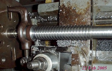
Below is the finished Acme thread. Not bad considering this is the first Acme thread I've ever done.
Presenting the finished mandrel...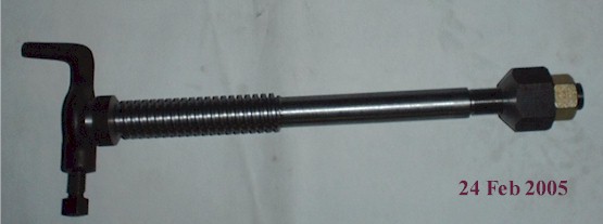
August 2005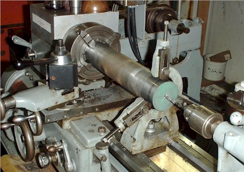
Now that farming has slowed to a pace that allows some machining time,
I have made some progress on the project. I have obtained round stock in the
necessary size (or nearly) and have drilled, bored and threaded the internal
dimensions. I would not hesitate to recommend Lindsay
Publications reprint of Deep Hole Drilling for information on this somewhat
specialized subject. The lathe is far and away the best method for accurate deep
drilling since the work must rotate and the drill stay stationary. A drill
press cannot be used for this type of drilling. I do not own and cannot afford live
lubricant fed gun drills so starting with a extra long (8" overall)
1/8" drill bit, 4 jaw universal chuck and steady rest I used the tailstock to peck
drill just over half way. This is a very tedious operation as you must back the bit
out often to clear the chips. I didn't dare cut more than 1/8" per cycle.
Breaking a bit off in the work at this point is not an option, I got it stuck once but
managed to recover it whole. After reaching half way I turned the part over, dialed
it in for accuracy (the stock must always turn as straight and true as possible)
and peck drilled until the bit broke through to the other hole. Mind boggling how
that works. This is by far the deepest drilling I have successfully executed. :)
After establishing the pilot hole I stepped up in drill size until I
could no longer afford large, long, high priced drills and then went to the boring bar
when I could get it to fit in the hole. Due to alot of vibration in my toolbit
during the internal threading, the tool kept getting knocked loose which made that
operation an exasperating experience in trial and error. Ultimately I was successful
with the internal Acme thread, but nothing went smoothly during this process and I can
only assume that I ground my relief angles incorrectly. A light duty lathe is not
very forgiving of such mistakes. In retrospect, I believe that the steady rest
was not tight enough and allowed for increased chatter, so the vibration was in the work
not the tool.
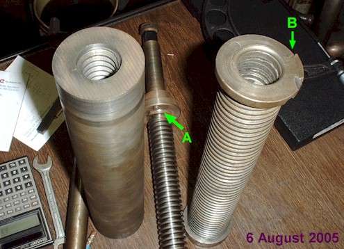
The first stage inner Z screw incorporates an engagement dog ('A'
seen at right) which catches in a spiral ramp cut into the top of the outer Z
screw. This dog must engage a catch ('B' at right) in the top deck of the
outer Z screw, but must not contact the ramp through which it approaches the catch.
In order to maintain accuracy the weight of the knee must always be on the threads, not
the ramp. You may be able to see in the picture where the dog had previously struck
(and cracked) the ramp on the old part at about the 11 o'clock position.
The ramp obviously must have the same pitch as the threads do and the new outer Z screw
must have the internal threads machined in order to determine where the ramp pitch must
start. I installed the old inner screw into the new part once the internal threads
had been cut and advanced it until the dog touched. I then backed the inner screw
out an eighth of a turn figuring this ramp starting position with an end position about
180ş around would allow for significant wear and yet still give a positive engagement at
the catch.
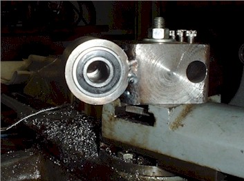 For the machining of this catch ramp I decided to use the lathe spindle to rotate the part
while the lead screw duplicates the Acme thread lead. To relieve the part for this
cut I constructed this live roller bearing spindle housing to go on the compound
rest. I am now making the spindle to drive a half inch end mill through this housing
from a hand drill. I can then use the compound advance to precisely mill the deep
end of the catch ramp and so relieve the ramp cutter at the end of the cut. Crazy
huh?
For the machining of this catch ramp I decided to use the lathe spindle to rotate the part
while the lead screw duplicates the Acme thread lead. To relieve the part for this
cut I constructed this live roller bearing spindle housing to go on the compound
rest. I am now making the spindle to drive a half inch end mill through this housing
from a hand drill. I can then use the compound advance to precisely mill the deep
end of the catch ramp and so relieve the ramp cutter at the end of the cut. Crazy
huh?
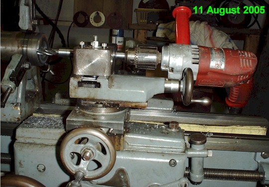 Originally, I intended to plunge mill the relief for a straight side cutting lathe tool to
cut the ramp, but I found that the torque required to cut with the lathe tool was too high
for me to rotate the spindle by hand (belts would slip on contact) and powered cutting was
too uncontrolled to stop where I wanted it to. I ended up cutting the entire
ramp with the end mill and it worked like a charm. My set up is shown at
right. I ran the drill while advancing the spindle by hand. The half nuts are
engaged and the lead screw advances the cutter as the spindle turns. Go slowly to
give the end mill plenty of time. The compound rest is set at 90° and provides the
fine feed control for each pass. The half nuts remain engaged throughout the entire
operation and the tool is backed out by spinning the spindle in reverse. When
backing out to start the next cut be sure to back out the compound rest to provide
clearance for lash in the lead screw (all screws have some), then readvance the compound
rest to the previous position plus whatever feed you are using.
Originally, I intended to plunge mill the relief for a straight side cutting lathe tool to
cut the ramp, but I found that the torque required to cut with the lathe tool was too high
for me to rotate the spindle by hand (belts would slip on contact) and powered cutting was
too uncontrolled to stop where I wanted it to. I ended up cutting the entire
ramp with the end mill and it worked like a charm. My set up is shown at
right. I ran the drill while advancing the spindle by hand. The half nuts are
engaged and the lead screw advances the cutter as the spindle turns. Go slowly to
give the end mill plenty of time. The compound rest is set at 90° and provides the
fine feed control for each pass. The half nuts remain engaged throughout the entire
operation and the tool is backed out by spinning the spindle in reverse. When
backing out to start the next cut be sure to back out the compound rest to provide
clearance for lash in the lead screw (all screws have some), then readvance the compound
rest to the previous position plus whatever feed you are using.
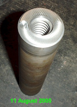 Here
is the completed ramp...
Here
is the completed ramp...
 After mounting the new screw on the centering mandrel and cutting the OD to the nominal
thread diameter I finally cut the external threads. The base bushing had a
nonstandard thread which required a slightly smaller minimum diameter so I had to cut
beyond the standard Acme thread depth in order for the parts to mate without interference,
but everything else went smoothly.
After mounting the new screw on the centering mandrel and cutting the OD to the nominal
thread diameter I finally cut the external threads. The base bushing had a
nonstandard thread which required a slightly smaller minimum diameter so I had to cut
beyond the standard Acme thread depth in order for the parts to mate without interference,
but everything else went smoothly.
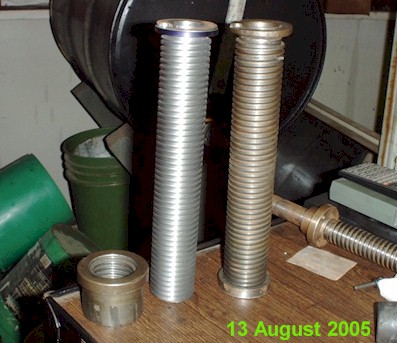
Finally, the old part meets the new. Not too shabby for a beginner. I will reuse the old base ring on the new screw.
 Igor,
throw the switch....
Igor,
throw the switch....
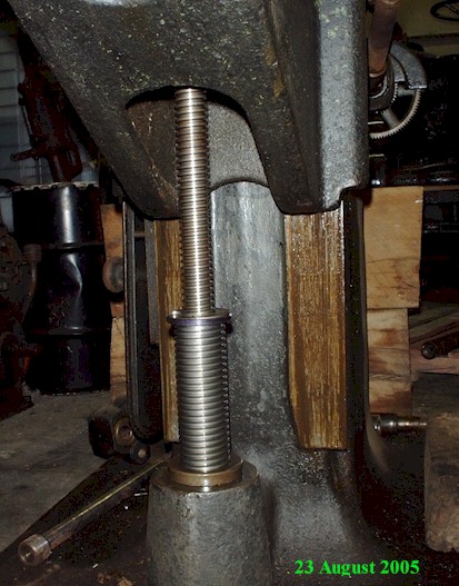
IT'S ALIVE!!!
The next winter's project is to find out what's wrong with the rear horizontal spindle bearing. It creates a great deal of heat after running for a while. To be continued...
Thanks to Mr. Kevin Lopez for generously donating both the mill and vertical spindle attachment (pictures to follow soon) as well as other related items. Thanks also to Mr. David Leaverton for supplying the restored Logan 820 lathe that made it all possible. Thanks also to Hendeyman from www.practicalmachinist.com for corrections
Suggestions are welcome here
Visit us at: Plain View Farms
Home Email Parts Hagie Hi-Clearance
Page last updated 15 June, 2009
webmaster@plainviewfarms.com
Copyright ©2009 Plain View Farms, LLC